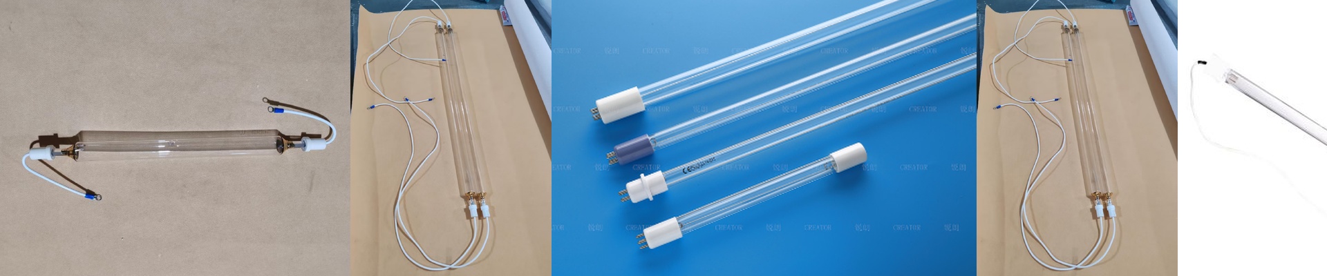
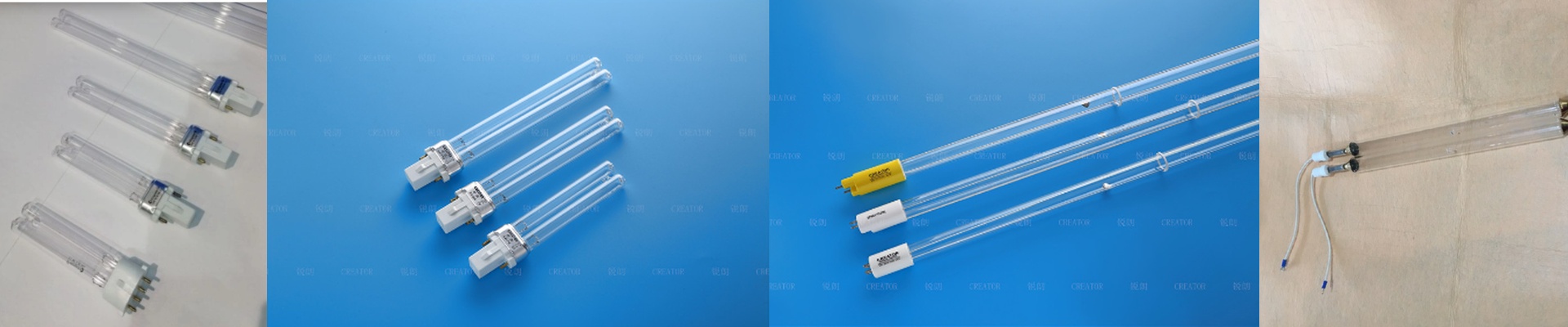
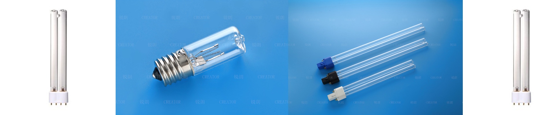
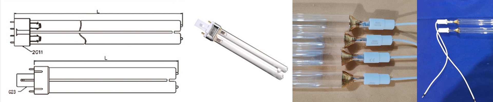
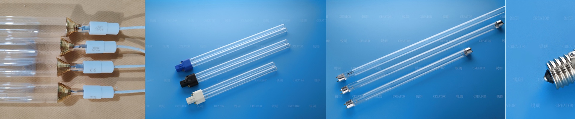

You’re on the plant floor, eyes flicking between the flow meter and the UV intensity readout. The system’s running, but the disinfection numbers are drifting. Is the lamp finally sliding into its decline phase, or has the water changed on you? No guessing. It comes down to spectral output, irradiance, and the aging curve of the lamp. In big water treatment setups, UV disinfection can fail without much warning. Output starts to fall before the lamp even darkens. Microbe reduction gets spotty. Alarms go off, and you’re left chasing a black box. We build UV lamps for water treatment because uptime and validated dosing are the only acceptable realities. The core question is practical: can the lamp hold the germicidal energy you need, day after day, at full flow?
What matters, technically
Large-scale water treatment UV systems lean on low-pressure mercury vapor lamps engineered for stable germicidal output at 254 nm. The wavelength is fixed by physics. What you control is output stability, lamp life, and system efficiency.
- Spectral output and germicidal effectiveness: The main output at 254 nm hits microorganisms where it counts—their nucleic acids. Disinfection is about absorbed dose, not broad-spectrum flash.
- UVC output and irradiance: Output is measured in millijoules per square centimeter (mJ/cm²), while peak irradiance is measured in milliwatts per square centimeter (mW/cm²). Delivered dose equals irradiance multiplied by exposure time. In high-flow installs, hitting the target dose means keeping irradiance stable across the entire quartz sleeve and the reactor cross-section.
- Lamp aging and output decay: Mercury lamps lose output over time due to electrode wear, mercury depletion, and quartz sleeve degradation. We call out lamp life by end-of-life (EOL) output, typically when UVC output drops below 80% of the initial rated output. In practice, plan replacements before the curve starts to drop off hard.
- Quartz sleeve transmission and fouling margin: The sleeve has to transmit 254 nm efficiently. Thickness, purity, and surface finish drive transmission. Real water carries iron, manganese, hardness, and organics. Fouling cuts transmission. Design in cleaning cycles or wiping mechanisms, and size lamps to cover the fouling margin.
- Power density, voltage, and arc length: Lamp power is set by arc length and current density. Match lamp voltage and ballast to the reactor design. A mismatch leads to unstable operation, lower output, and a shorter lamp life.
- Ozone-free operation: Low-pressure lamps are inherently ozone-free at 254 nm. That matters for safety, material compatibility, and avoiding secondary oxidation headaches in distribution.
- Ballast and ignition reliability: Electronic ballasts deliver stable current and controlled ignition. Repeated hot restarts stress electrodes. For continuous duty in large systems, constant power with controlled ignition helps extend lamp life.
Why this works in the field
Large-scale water treatment runs on continuous flow, shifting water quality, and long service intervals. The UV lamp has to perform under those constraints, and the system has to deliver traceable, repeatable dosing.
- Stable dose at variable flow: When flow goes up, exposure time goes down. Stable lamp output and well-tuned hydraulics keep dose inside the validated window. When flow drops, the system needs to avoid overdose without cycling lamps too much.
- Consistent microorganism inactivation: UV dose sets log inactivation. For target pathogens, the dose requirement is well-defined. Hold output at 254 nm, and inactivation stays predictable, regardless of chemical doses or pH swings.
- Long lamp life cuts maintenance windows: Lamps that maintain stable output over 9,000 to 12,000 hours mean fewer reactor shutdowns. Fewer shutdowns translate to fewer labor hours, fewer gasket replacements, and lower risk of bypassing untreated water.
- Energy efficiency at scale: UV disinfection runs on electricity. Lamps matched to efficient ballasts keep watts per liter treated in check. Stable output across the lamp life avoids the hidden energy cost of compensating for decline by ramping power or cutting flow.
- Monitoring and validation readiness: UV sensors calibrated to 254 nm give real-time intensity readings. Lamps with predictable aging curves let you set replacement schedules based on intensity thresholds, not guesswork.
The details that bite you if you ignore them
Water treatment UV is simple in principle, but it comes with real installation and operating constraints.
- Reactor geometry and sleeve fit: Output only matters if the water actually sees it. Lamp-to-sleeve spacing, sleeve diameter, and reactor baffling set the intensity distribution. Retrofits have to match dimensions and tolerances. An oversized sleeve drops irradiance. An undersized one creates hot spots and stresses the sleeve.
- Water quality and fouling control: Hardness, iron, manganese, and tannins deposit on sleeves. Those deposits knock down 254 nm transmission faster than you’d think. Plan on periodic cleaning—mechanical wiping or chemical wash. Build in a performance reserve of 10% to 20% to cover fouling.
- Temperature and flow effects: Lamp output depends on temperature, and sleeve temperature is set by flow and ambient conditions. Low flow can overheat the sleeve and drop output. High flow cools the sleeve and can nudge output down a bit. Hydraulic design should keep sleeve temperature within the lamp’s rated window.
- Lamp orientation and mounting: Horizontal, vertical, and angled mounting change convection and temperature distribution. Stick to the reactor manufacturer’s orientation limits. Get it wrong, and you stress end caps and risk leaks.
- Electrical compatibility and ballast matching: Lamp voltage and ballast current must match. Mismatched ballasts push the lamp outside its design curve, accelerating electrode wear and output decay. Verify connector types, pinouts, and power ratings.
- UV sensor calibration and placement: Sensors read intensity at a point. That reading isn’t the average across the reactor. Calibrate sensors annually and place them where they represent the critical dose path. Older sensors drift. Treat intensity trends as a system signal, not a single-point verdict. If your system is trending toward lower intensity, start with sleeve cleanliness, sensor calibration, and ballast behavior before you assume the lamp is done. When the lamp truly hits end-of-life, replace it with a unit specced for the reactor geometry and your water matrix. Large-scale water treatment doesn’t have room for ambiguity. It rewards stable 254 nm output, predictable aging, and dosing you can verify. That’s the standard we build into the lamp—and the standard you run every day.